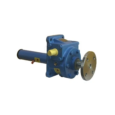
Multi Stage Linear Actuator features a simple structural design with low operational learning barriers. Compliance with standardized operation eliminates the vast majority of equipment faults, securing long-term stable actuator performance and extending usable service life. The full operational workflow is divided into five sequential stages: installation and fixing, wiring connection, no-load trial testing, formal loaded operation and post-operation shutdown storage. All procedures adhere to electrical safety standards and equipment rated parameter specifications.
Stage 1: Installation and Fixing (Foundation of Stable Operation)
Prior to installation, confirm actuator specifications, travel length and load capacity match target application requirements. Select vertical or horizontal installation based on operational demands. Tilted, suspended and eccentric mounting configurations are strictly prohibited. Choose a flat, rigid mounting base and fasten both actuator end connectors securely with matching fixing bolts to eliminate housing wobble or offset after installation. Ensure force bearing remains centered along the actuator's central axis during telescoping motion, with no lateral pulling or pushing loads. After installation, inspect the full telescoping travel path to confirm zero obstructive foreign objects that would cause collision or jamming during motion.
Stage 2: Wiring Connection (Guarantees Electrical Operation Safety)
All wiring work must be completed with power fully disconnected to eliminate live-wiring safety hazards. Match power supply voltage to the voltage rating marked on the actuator nameplate, differentiating DC and AC models - power connection with mismatched voltage ratings is strictly forbidden. For DC multi-stage actuators, strictly separate positive and negative wiring terminals and connect them to matching power supply and controller ports. Reverse polarity wiring reverses the actuator's extension and retraction direction. For models equipped with limit switch, speed regulation or wireless remote control functions, connect wiring to corresponding ports per product user manuals, ensuring tight secure wiring connections free of looseness or exposed bare copper wire to prevent short-circuit and electric leakage faults. Wrap all wiring joint connections with insulating tape post-wiring to complete line protection.
Stage 3: No-Load Trial Operation (Troubleshoot Basic Mechanical and Electrical Faults)
No-load testing is mandatory for first-time installation or equipment restart after long-term idle storage - conduct all motion testing with zero applied load. Activate control switches to test extension and retraction motion, observing uniform telescoping speed, smooth unobstructed motion and absence of abnormal noise or vibration. Focus on verifying upper and lower limit switch functionality, confirming automatic precise power cutoff at maximum/minimum travel limits without over-travel motion or mechanical rebound. Repeat trial cycles 3–5 times; only after consistent flawless motion performance may loaded operation proceed.
Stage 4: Formal Loaded Operation (Standardized Working Condition Compliance)
Strictly operate within the actuator's rated load capacity during all formal work, eliminating overload, offset eccentric load and instantaneous impact load. Never forcibly drag or squeeze the actuator mechanism. Execute gentle gradual start-stop control, avoiding frequent instantaneous start-stop and high-speed reciprocating impact motion to minimize abrasion of internal transmission components. Continuously monitor actuator operating status during work; immediately cut off power supply and shut down the unit upon detecting abnormal noise, violent shaking, mechanical jamming or excessive motor overheating. Troubleshoot all faults completely before resuming operation - never operate the actuator with confirmed functional abnormalities.
Stage 5: Post-Work Shutdown & Storage Maintenance
After completing single-batch operation tasks, adjust the Multi Stage Linear Actuator to a mid-stroke neutral position, avoiding long-term retention at full extended or fully retracted limit positions. This eliminates sustained structural mechanical stress and reduces component fatigue wear. Cut off power supply immediately post-operation and organize all connecting wiring neatly to prevent wire pulling, abrasion and insulation damage. For continuous long-duration operation, pause work every 4–6 hours to allow the motor to rest and cool down, preventing activation of overheat protection or permanent motor burnout. Pair daily operation with periodic cleaning and lubrication maintenance to maximize actuator operational efficiency and overall service life.