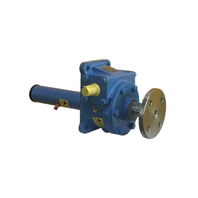
Multi-unit screw jack synchronous lifting systems are widely used for industrial platform lifting, equipment positioning and structural leveling. Both standard and stainless steel heavy-duty screw jacks tend to generate subtle height errors, asynchronous speed and platform tilting after long-term operation. Minor sync deviations reduce positioning accuracy, while severe imbalance causes uneven load bearing, structural jamming, component wear and unexpected equipment shutdown.

Most synchronous failures stem from cumulative errors in mechanical assembly, transmission clearance, load distribution and control matching, rather than product defects. This article summarizes the key causes of multi-jack sync deviation and practical high-precision correction techniques to help engineers achieve stable, long-term synchronous lifting and simplify on-site maintenance.
1. Core Root Causes of Multi-Screw Jack Synchronization Deviation
Multi-jack synchronization deviations mainly come from three key factors: mechanical transmission tolerance, on-site installation and load imbalance, and electrical control response errors. These cumulative tolerances break the consistency of lifting stroke and speed across multiple jack units.
1.1 Mechanical Transmission Cumulative Clearance Error
Mechanical backlash is the primary cause of asynchronous operation. Worm gears, trapezoidal screws, couplings and transmission shafts all carry inherent manufacturing and assembly tolerances. In linked multi-jack systems, these tiny gaps accumulate rather than offset during operation.
Frequent start-stop and forward-reverse lifting amplify inconsistent backlash among individual units, creating obvious stroke deviation. Long-term operation increases gear and screw wear, further widening synchronization errors over time.
1.2 Transmission Shaft and Coupling Phase Misalignment
For mechanically linked screw jack systems, transmission shaft coaxiality and coupling phase consistency determine sync accuracy. On-site vibration and improper installation commonly cause shaft deflection, universal joint angle deviation and phase misalignment.
Even minor phase differences create cumulative stroke gaps per lifting cycle, leading to platform tilting and uneven load bearing. Loose shaft keys and clamping gaps also cause slippage under heavy loads, resulting in single-unit lag and overall system desynchronization.
1.3 Unbalanced On-Site Load Distribution
Most sync issues result from unbalanced on-site loads. Offset workpiece gravity centers and inconsistent friction at support points create uneven pressure distribution, with some jacks operating under heavy loads and others under light or no load.
Heavily loaded jacks run slower due to higher resistance, while light-load units lift faster, producing real-time sync deviation. Persistent load imbalance causes inconsistent component fatigue wear, leading to irreversible accuracy loss.
1.4 Installation Level and Structural Deformation Errors
Uneven mounting foundations, inconsistent installation heights and bracket deformation easily cause zero-point offset for individual jacks, a commonly overlooked debugging issue.
Initial zero drift expands as lifting stroke increases, creating noticeable height differences. Heavy-load platform deformation also triggers offset displacement of single jacks and damages overall synchronization.
1.5 Electrical Control and Sensor Response Deviation
Electric synchronous systems face deviations from inconsistent motor speed, VFD response delays and encoder feedback errors. Identical control signals still produce subtle speed and signal sampling differences across individual units.
Without real-time dynamic compensation from the PLC system, these minor differences accumulate, causing continuous small-range sync deviation during reciprocating lifting.
2. High-Precision Synchronization Correction & Calibration Techniques
The following targeted calibration methods effectively eliminate cumulative errors, restore multi-jack synchronization accuracy and ensure stable long-term operation. These practical techniques apply to both mechanical linkage and electric synchronous systems.
2.1 Eliminate Transmission Backlash & Standardize Mechanical Clearance Calibration
Unify internal clearance for all jacks in the synchronous group via consistent pre-tightening adjustment, standardizing backlash tolerance and eliminating wear-induced gaps between units.
Replace severely worn gears, screws and bearings promptly. For new systems, run full-stroke idle reciprocation to eliminate assembly clearance and ensure uniform transmission sensitivity.
2.2 Recalibrate Transmission Shaft Phase & Coaxiality
For mechanical linkage systems, reset all jacks to a unified zero reference point after disconnecting couplings. Reinstall transmission components strictly by phase marks to guarantee consistent phase angles across all units.
Control shaft coaxiality and parallelism errors within 0.5°, adjust supports to avoid excessive universal joint deflection, and fasten all couplings and shaft keys with anti-loosening measures to prevent load slippage.
2.3 Optimize On-Site Load Balance & Stress Distribution
Correct platform and workpiece placement to balance gravity center and evenly distribute load pressure on all screw jacks.
For fixed center-of-gravity conditions, fine-tune individual jack resistance via torque balance debugging to unify lifting speed. Adopt load-sharing structures for large-span systems to buffer stress concentration and maintain synchronous force feedback.
2.4 Uniform Zero-Point Calibration & Foundation Level Correction
Regularly recalibrate system zero points by retracting all jacks fully, then level and adjust mounting bases to unify installation benchmarks and eliminate foundation-induced height errors.
Record unified zero-point data as a fixed benchmark for routine maintenance, avoiding repeated debugging errors and benchmark confusion.
2.5 Dynamic Electrical Synchronization Compensation & Intelligent Debugging
Optimize PLC synchronous programs with dynamic deviation compensation. Install high-precision encoders on each jack for independent real-time position monitoring.
Set a reasonable sync tolerance threshold for automatic speed and frequency micro-compensation. Unify motor and drive parameters to eliminate response delays and achieve closed-loop synchronous control.
2.6 Establish Regular Synchronization Maintenance Mechanism
Establish periodic calibration cycles to inspect transmission clearance, shaft phase, zero offset and load balance every 1–3 months, correcting minor deviations early.
Archive all calibration data to support fault diagnosis and precision maintenance, effectively preventing major sync failures and equipment downtime.
3. Key Benefits of Standard Synchronization Calibration
Effectively eliminate platform tilting, jamming, and stroke deviation problems, improving lifting and positioning accuracy
Balance the load of each screw jack unit, reduce local component wear, and extend overall equipment service life
Stabilize system operation status, reduce failure rate and on-site maintenance costs
Meet high-precision industrial production and automated positioning technical requirements
Conclusion
Screw jack synchronization deviation is a comprehensive error caused by superposed mechanical, installation, load and control factors. Fundamental resolution relies on targeted mechanical calibration, load optimization, electrical dynamic compensation and regular maintenance. Standard calibration ensures long-term high-precision synchronous operation, especially critical for stainless steel screw jacks working in corrosive, humid and heavy-duty industrial environments.